 here.
here.
When I started to make a DSP transceiver I faced a challenge of selecting the DSP processor and CODEC chip. The initial selection was DSP56001A and CS4222. The main criteria was availability. I made a DSP board (click here for the photo) and wrote a software for it. It works, but I realized that 10.5 MIPS that DSP56001A provided was too slow for my plans. Fortunately I have found a suitable solution the series of the audio DSP for consumer applications DSP5636x was just what I needed.
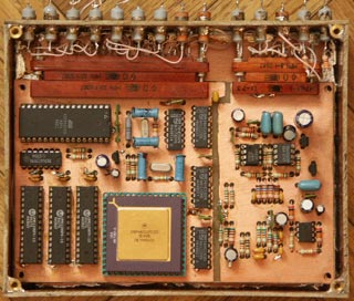
The DSP module is shown on this picture. You can see an analog section (on the left) and digital (on the right) with the separeted ground planes. The 24 bit DSP56362 is mounted on the sub-board (it simplifies PCB design). The DSP software is stored in the 256KByte AT29F020 flash memory chip.
The CODEC chip (CS4223) is mounted on the bottom side of the PCB. The OP amplifiers the provide differential feed to ADC and filters DAC output are high quality OPA2134A. I have tryed many others, but these are the best here.
The DSP software is written in assembly language. The filters coefficients were calculated using MATLAB program. The DSP is operating at 120 MHz (it is capable of up to 120MIPS/MMACs and 600 MOPS). The current version of software uses approx. 40% of its processing power.
The control processor "talks" to the DSP processor via the SPI bus.
The more detailed information (including various block diagrams and DSP algorithms discussions will be posted here later (check the News section periodically).
The schematics of the DSP board is here.


 Made in Ukraine