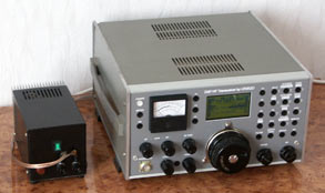
The T03DSP High Performance Transceiver with DSP IF
processing
Designed by Oleg Skydan UR3IQO
Introduction
This WEB site is dedicated to the design of the HF
transceiver with DSP IF processing.
This design is the result of the more than 2 years
experimenting, writing software and designing hardware.
What I wanted to do
The goal of this project was to build a high performance
HF transceiver with DSP IF processing. I did not try to archive as high
parameters as possible, I just tried to get most from the available technology
(i.e. mechanical and electrical parts and assembly technology). I tried to keep
the design as simple as possible. The design widely uses "software" techniques
that allows easy modifications and opens new possibilities (especially for such
experimenter like I am :).
What I have now
The transceiver hardware is completed and the first version of software too (but I
am actively improoving it). You can view the measured specifications here.
Computers, computers, computers...
As I said before I have widely used "software"
techniques in this transceiver. There are two microcontrollers (first MSP430F149
is used as control processor and the second MSP430F123 - in synthesizer), one
DSP processor (Motorolla DSP56362 @ 120MHz) and one CPLD chip.
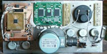
Just who is managing all this things ?
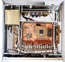
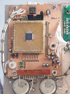 |
You can see the control board on this picture. Many SMT components are
on the bottom side of the board and under the MCU (MSP430F149) sub-board.
The control software is written mostly in C with some assembly
fragments. I have written a real time operating system specially for this
transceiver control program (you can visit it's WEB-site here), it saves a lot of
coding time and makes programming much more efficient. At the present
moment the control software has more then 15000 lines of C code. It
consumes 41KB of flash (I have 19KB more for further development
:). I used free msp430-gcc compiler.
|
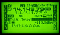
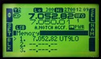
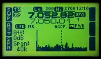
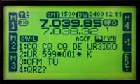
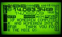
The information is diaplayed on the graphic LCD
(128x64) with yellow-green LED backlit. The control software uses mulilevel
menus and provides control for a lot of different
parameters.
More screeshoots are here.
And how much processing hourse power does it have
?
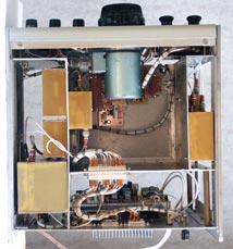
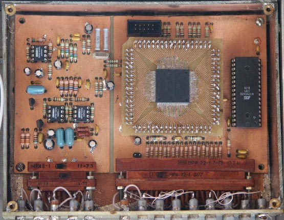 |
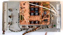
The DSP module is shown on this picture. You can see an analog section
(on the left) and digital (on the right). The 24 bit DSP56362 is
mounted on the sub-board (it simplifies PCB design). The DSP software is
stored in the 256KByte AT29C020 flash memory chip.
The DSP software is written in assembly language. The filters
coefficients are calculated using MATLAB program. The DSP is operating at
120 MHz (it is capable of up to 120MIPS/MMACs and 600 MOPS). The current
version of software uses approx. 40% of its processing power. The control
processor "talks" to the DSP processor via SPI bus.
For more information go to the DSP page.
|
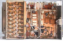
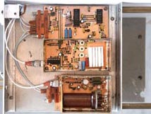
OK. Let's look inside...
The transceiver uses aluminium chassis and home
made PCB boards. Most boards are screened.
All materials provided here are copyright by
Oleg Skydan. In all cases, materials are
provided for the purpose of self education and training in Amateur Radio. No use
may be make for commercial purposes without permission of the author. Please
send any comments and questions to Oleg Skydan UR3IQO.

 Made in Ukraine